
Building the Easy Rotator Control ERC
It all started in 2008, when I visited the DF9GR stand at the Ham Radio event in Friedrichshafen. I wanted some means of controlling my rotator from the PC, especially during contests.
Rene DF9GR told me that the ERC would not work with my Yaesu G600RC, so I forgot about it until visiting his stand once again in 2010. This time he told me he had made some changes, and that it would now work!
So, I purchased the kit, and when I got home, I started to build it.
The kit comprised some very comprehensive instructions, including a full parts list, so the first job was to identify all the parts.
When building kits, it is always advisable to start with the resistors and then the capacitors. Next to get fitted were the parts that had to be fitted the right way round, ending up with the relays and IC sockets.
At this point, I followed the instructions, and made sure that I had the 5v present at the right place, and that was good.
The final step was to carefully fit the two IC’s.
For more info on the ERC, check out the website
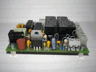
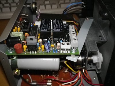
This is a picture I took of the completed kit:
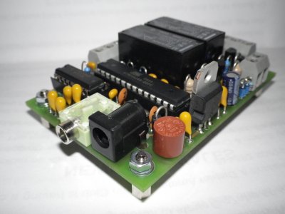
Another view:
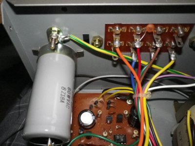
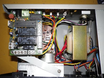
This is a view of the inside of my G600RC rotator controller:
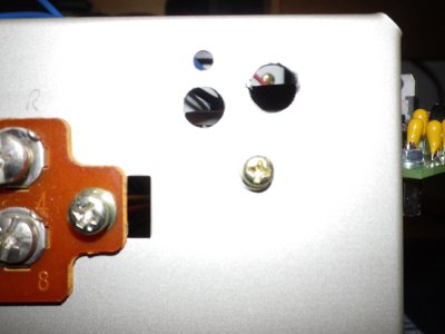
As there are two connections to the outside, two holes were needed in the case.
One for the 12v supply, and one for the data lead.
I used a card template, and then drilled the two holes.
When drilling the holes, it is important to leave enough clearance for the 7805 regulator!
As you can see, the 7805 regulator sticks up, so make the holes low enough to accomodate.
At the back of the controller housing, I used some stiff right-angled plastic, and fitted it over the screw that holds the plate for the wire connections on the back.
The front connection (dial side) was made with the removed bracket to allow the kit to fit inside.
There is a convenient hole on the metal housing of the gears, just at the top, towards the middle.
I used a small self-tapping screw to hold that end, and drilled a suitable hole to connect the stand-off on the kit.
Here is a view of the fitted kit from above.
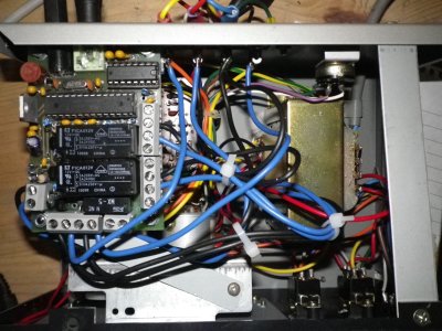
And the final step was to wire it all in!
With the Yaesu G600RC, the installation guide isn’t as clear as it could be. The blue and yellow dots marked “1” and “4” don’t need to be fitted at the switches.
It is far easier to fit them across the 26v tags on the transformer. Put the two “1’s” on the 26v tab, and the two “4’s” on the 0V tag.
BUT PLEASE NOTE that the output of the transformer is AC voltage, so you will need to remember this when you check which terminals have which voltages.
Some of G600RC controllers have 4 tags, while some have 5 tags, and they don’t always line up with the markings on the labels.
Make sure you have the correct 0V tag, and the correct 26V tag.
Again, some controllers vary and show 29V instead of 26V, and they probably read 30V with a meter.
The actual voltage is not critical, so long as you use the 0V tags and the 26 (or 29)V tags, and make sure you don’t use the tags marked 14V.
With the Yaesu G600RC, the installation guide isn’t as clear as it could be. The blue and yellow dots marked “1” and “4” don’t need to be fitted at the switches.
It is far easier to fit them across the 26v tags on the transformer. Put the two “1’s” on the 26v tab, and the two “4’s” on the 0v tag.
The rest of the wires can be soldered to the back panel of the wiring connector. Just make sure you get the numbers in the right order! Once you are happy with the layout, connect it to a 12v supply, and to your PC.
I am using Win7 Pro (32bit) on my shack PC, and it has one COM port, so I used this for the ERC.
The kit comes with a CD containing all the instructions, plus the DF9GR software, which you will have to use to calibrate the controller, plus a “lite” version of PSTRotator by YO3DMU.
You will need to calibrate the controller, so to do this, you must use the DF9GR software. Calibration is very easy, and doesn’t take too long. Just follow the on-screen instructions, and it will work nicely.
Once you have finished the calibration, click the button marked WRITE ERC, otherwise the settings may not be saved!
There is also an option to enter an azimuth for ” parking” the antenna.
I use this all the time, as I like my antenna to sit at 65 degress when not in use, as that presents a less obvious view of the antenna from the road.
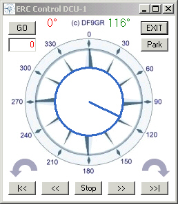
Now click on “ERC Control”, and you will get a compass like window, where you can type in a specific heading, or click anywhere on the compass rose, and the beam will turn!
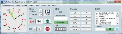
PSTRotator Lite is a slightly cut down version of the full software, but as far as I can see, the only part missing is the ability to use the software with other programs.
But, it does give you the ability to specify a locator square, DXCC entity (from a list, or just type in the prefix), go short or long path, and maybe most useful is the ability to create your own list of presents.
To see more on PSTRotator, go to the Homepage
This is the Service Tool, used to set up and calibrate the software:…………………And this is the ERC interface: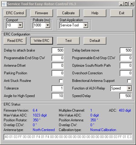
And here is what the PSTRotator interface looks like:
Any comments or suggestion, please send to
phil (at) gu0sup (dot) com